Design for manufacturability is the engineering practice of optimizing product designs to simplify fabrication, lower production costs, and minimize the need for revisions. This methodology integrates manufacturing considerations early in the development process to ensure that products are both functional and cost-effective to produce at scale.
Few things are more frustrating than a precision component that looks perfect on a screen but fails the reality test of the shop floor. When a complex design reaches the fabrication stage only to be sent back for revisions, the results are predictable; lead times stretch, material costs climb, and project momentum stalls. This friction usually stems from a disconnect between theoretical engineering and the practical constraints of metal forming, welding, and machining. Design for Manufacturability, or DFM, bridges this gap by integrating production insights directly into the initial drafting phase. In this guide, we will analyze the core principles of efficient fabrication and clarify the distinctions between manufacturing and assembly optimizations. You will also find a practical checklist designed to help your team lower production costs, eliminate unnecessary revisions, and ensure every part is built for maximum efficiency.
Understanding Design for Manufacturability (DFM) in Modern Fabrication
Design for manufacturability is more than an engineering theory; it is a proactive strategy to reduce overhead and minimize production bottlenecks. In the context of precision manufacturing and fabrication services, DFM involves analyzing a component's geometry, material choice, and assembly requirements specifically to ensure it can be produced repeatedly and cost-effectively. It serves as the bridge between a conceptual design and a physical part that can actually be built at scale.
Traditionally, many firms operated under a siloed approach, often described as throwing a design over the wall. Engineers would finalize a CAD model in isolation, only for the fabrication team to discover that the specified tight tolerances were unnecessary or that tool access was physically impossible for a standard CNC mill. This disconnect leads to expensive redesigns, wasted material, and significant project delays.
By integrating DFM early in the conceptual phase at our Ephraim facility, we bridge the gap between intent and execution. For businesses across Utah, this collaborative review ensures that prototypes transition to full-scale production without the friction of mid-stream changes. We look for opportunities to simplify complex features and align designs with standard tooling; this allows us to build reliably to operational requirements while keeping project timelines on track.
The Core Principles of Design for Manufacturability

To move beyond high level theory, we categorize design for manufacturability into five essential pillars. Each pillar represents a critical decision point where engineering choices directly impact the final invoice and production timeline at our Ephraim facility.
1. Process Selecting the fabrication method early is vital because it dictates the entire cost structure. For example, choosing CNC machining for a component that could be produced via sheet metal fabrication often leads to unnecessary expenses. A part requiring a complex internal pocket might require multiple setups on a 5-axis mill, whereas a redesign using a laser-cut base and a press-brake bend achieves the same function at a fraction of the cost. We evaluate whether the geometry allows for standard tooling access to minimize custom fixtures and setup time.
2. Design We focus on simplification and the reduction of part counts. Every unique part number requires separate procurement, quality inspection, and setup. By consolidating three separate brackets into a single multi-bend component, we eliminate the need for welding or fasteners. This reduces human error and ensures the final build is repeatable at scale.
3. Material Effective precision manufacturing and fabrication services rely on selecting materials that balance performance with machinability. We look for common metal gauges and alloys that are readily available in the regional Utah market. Using a specialized, hard-to-source alloy when a standard 6061 aluminum or 1018 carbon steel suffices can lead to long lead times and increased tool wear.
4. Environment The design must account for the end-use environment, including thermal expansion and corrosion resistance. These factors influence the choice of surface finishes or coatings, which must be factored into the initial dimensions to ensure the part remains within tolerance after treatment.
5. Compliance Reliable production requires adhering to industry standards and safety regulations from the outset. By integrating compliance checks into the DFM phase, we ensure that components meet operational requirements without needing expensive structural revisions after the first production run.
Design for Manufacturing DFM and Design for Assembly DFA: What is the Difference?
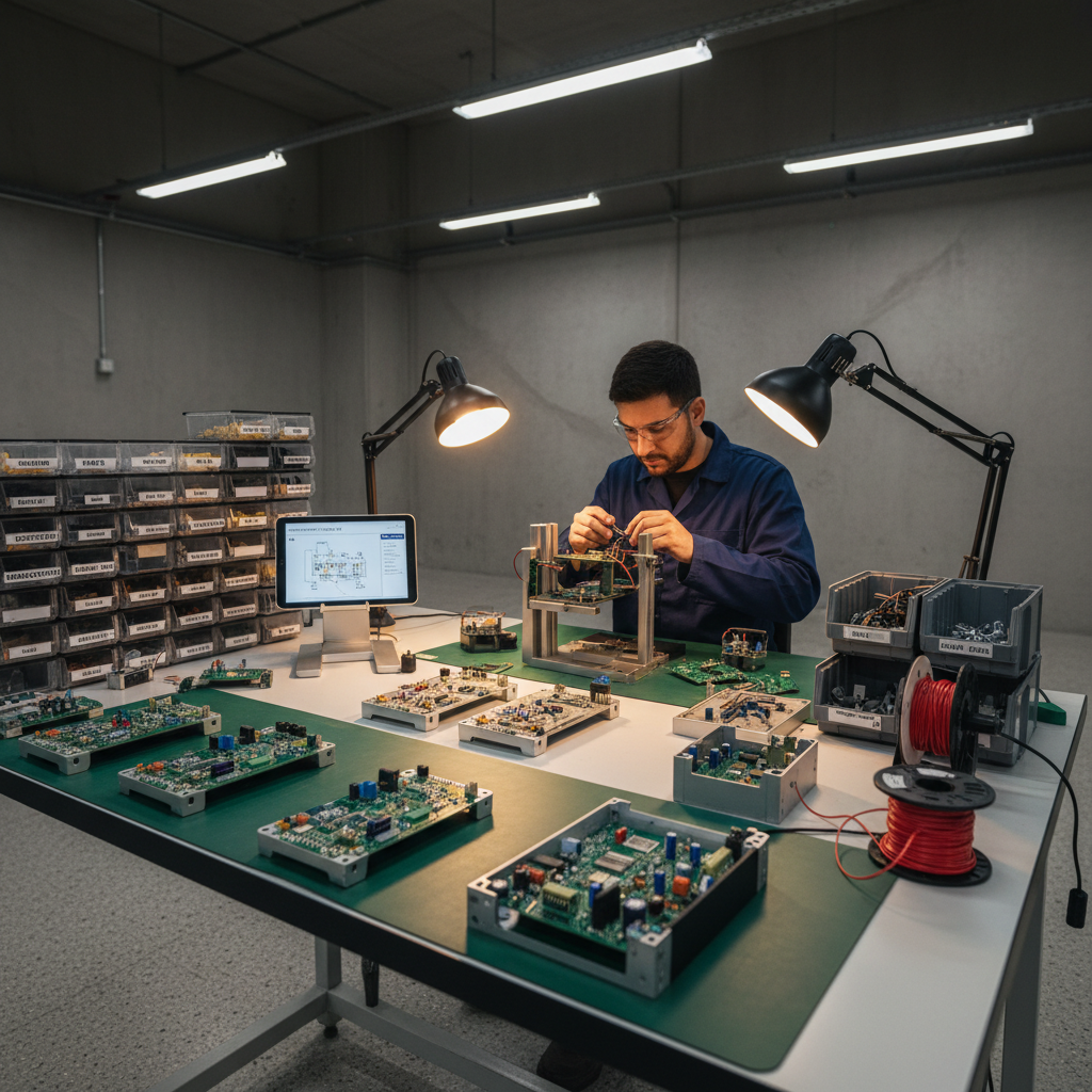
While the terms are often used interchangeably, distinguishing between Design for Manufacturing (DFM) and Design for Assembly (DFA) is critical for optimizing a production run. DFM focuses specifically on the ease and cost-effectiveness of creating individual components. It addresses technical variables such as tool access, material waste, and machining time for a single bracket or housing. Conversely, DFA centers on the efficiency of the assembly process. It evaluates how those components interact and how quickly a technician can combine them into a finished product.
At Anderson Manufacturing, we integrate these methodologies into a unified approach known as Design for Manufacturing and Assembly (DFMA). Because we provide precision manufacturing and fabrication services that often include both part creation and final assembly, we see firsthand how a part that is easy to machine can still be a nightmare to install. Integrating both ensures that the cost savings realized during individual part fabrication are not lost during the labor-intensive assembly stage.
Effective DFA often involves minimizing the variety of fastener types. If an assembly requires three different sizes of Hex bolts, a technician must switch tools and manage multiple hardware bins, increasing labor time and the risk of error. By standardizing to a single fastener size across the entire build, we streamline the workflow. Additionally, we look for opportunities to incorporate self-aligning features, such as tabs and slots or asymmetrical mounting patterns. These features ensure that parts can only be assembled in the correct orientation, virtually eliminating human error during the final build phase. To see how these principles apply to your specific project, you can contact Anderson Manufacturing for a design review.
Fabrication Specific Guidelines to Lower Production Costs
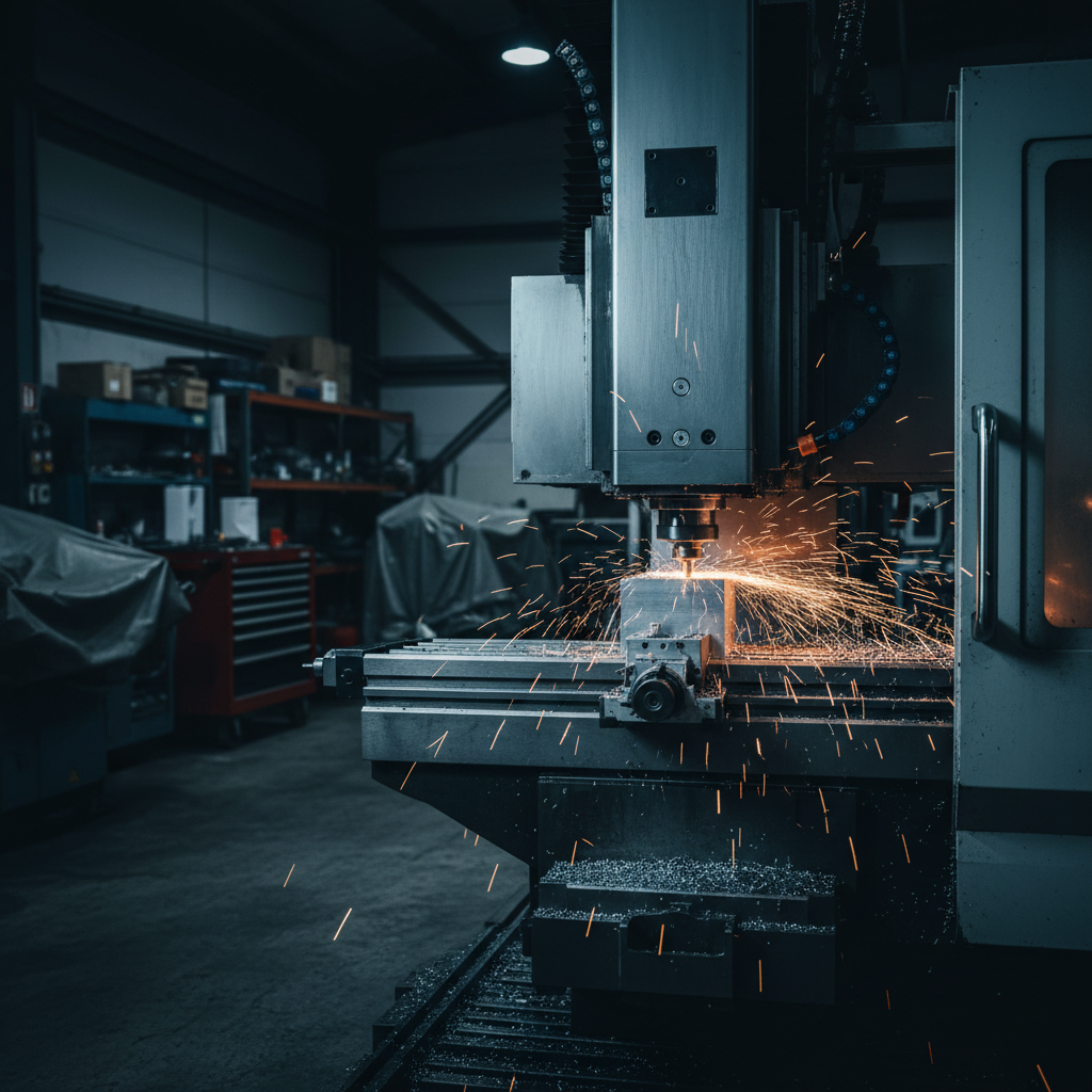
Applying design for manufacturability at the granular level requires moving beyond CAD models to consider the physics of the shop floor. For engineers looking to aggressively lower production costs, a few technical adjustments during the design phase yield the highest return on investment.
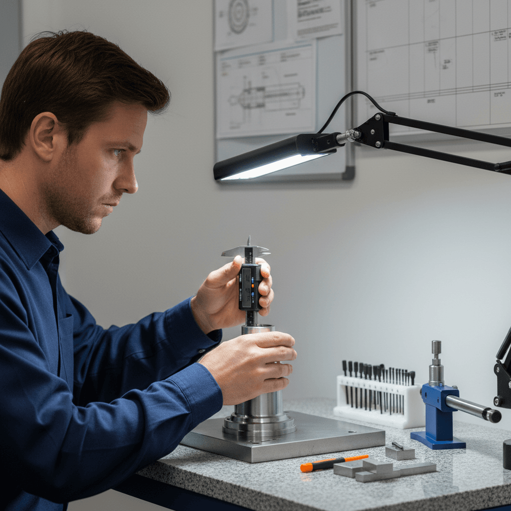
1. Optimize Tolerances for the Application Over-tolerancing is a primary driver of unnecessary fabrication costs. While a +/- .001 inch tolerance is achievable, it often requires specialized gauging, slower feed rates, and a higher scrap allowance. Unless a feature is a critical press-fit or a bearing surface, relaxing the tolerance to +/- .005 or +/- .010 inches allows for standard machining speeds and reduces the need for expensive secondary operations like grinding. Designing for the widest possible tolerance that maintains functional requirements directly translates to lower unit costs.
2. Standardize Materials and Gauges Material selection should reflect local market availability in Utah to avoid long lead times and shipping surcharges. We frequently see designs that call for obscure alloys or non-standard thicknesses that require custom mill runs. Utilizing common materials like 6061-T6 aluminum, 1018 carbon steel, or 304 stainless steel in standard fractional thicknesses ensures faster procurement and better pricing. When designing sheet metal components, sticking to standard gauges like 11, 14, or 16 gauge allows us to pull from existing stock rather than placing special orders for specific decimal thicknesses.
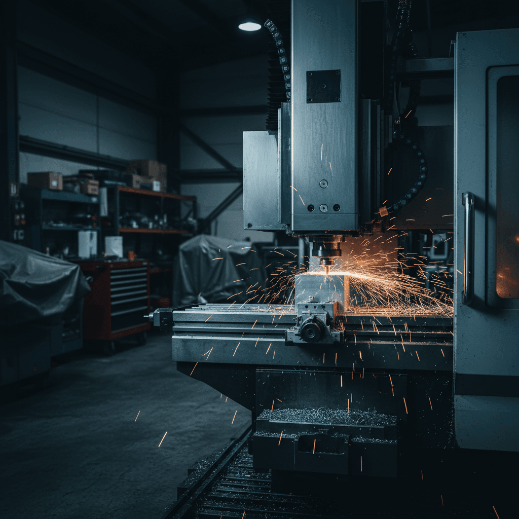
3. Geometric Considerations for Fabricability In sheet metal fabrication, internal bend radii should generally equal the material thickness to prevent cracking and ensure repeatable results on the press brake. Sharp internal corners in CNC machining should be avoided wherever possible. Because cutting tools are round, they cannot create a perfectly square internal corner without specialized EDM or broaching processes. Designing with a radius slightly larger than the cutting tool prevents tool chatter and improves surface finish. Additionally, prioritize tool access by maintaining a length to diameter ratio of 3:1 for internal cavities; deeper pockets often require slower speeds and increase the risk of tool deflection.
By focusing on these technical specifics, you ensure that our precision manufacturing and fabrication services are utilized for efficient production rather than correcting preventable design flaws. If you have questions about specific feature constraints, you can contact Anderson Manufacturing to discuss the technical requirements of your project before finalized drawings are issued.
A Practical DFM Checklist for Fabrication and Assembly
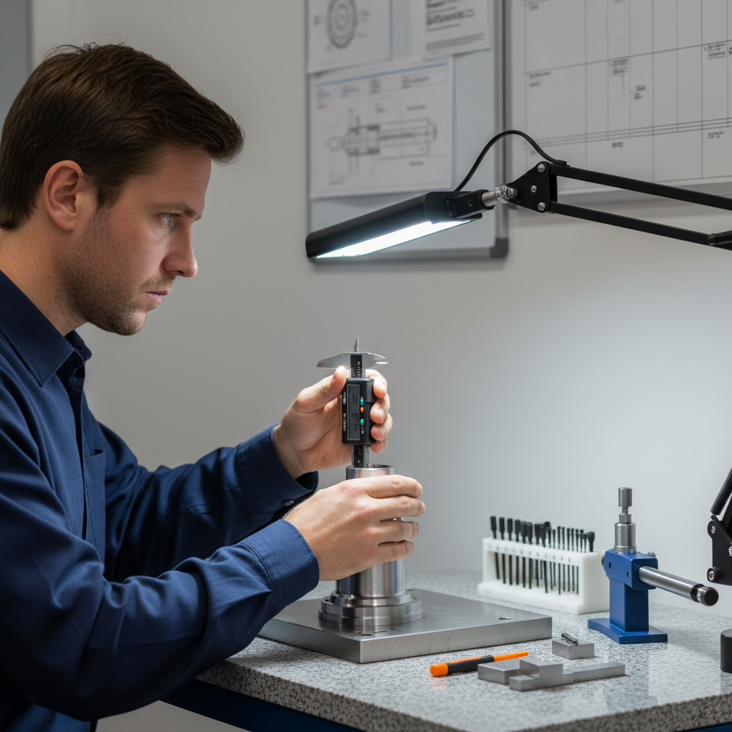
Moving from technical principles to a finalized design requires a systematic review. Before submitting a Request for Quote (RFQ) for precision manufacturing and fabrication services, running a standardized checklist ensures your design is ready for scalable, repeatable production. This step prevents the back and forth revisions that often delay project kickoffs at our Ephraim facility.
Use the following criteria to evaluate your fabrication and assembly readiness:
Raw Material Availability: Confirm that the specified alloy and gauge are standard stock items in the regional market. Custom mill runs for non-standard thicknesses or specialized alloys significantly increase lead times and cost.
Hole-to-Edge Distances: Ensure all holes are placed at a distance of at least 1.5 to 2 times the material thickness from any edge or bend line. This prevents material deformation or tearing during the punching and laser cutting processes.
Uniform Wall Thicknesses: Maintain consistent wall sections throughout the part. Significant variations in thickness can lead to internal stresses, warpage, or structural weaknesses during the forming and cooling phases.
Thread Depths and Blind Holes: Specify thread depths no deeper than 2 to 3 times the bolt diameter. For blind holes, ensure the drilled depth provides sufficient clearance for the tap to avoid tool breakage and ensure full thread engagement.
Finishing Requirements: Clearly define post-process needs like powder coating, plating, or anodizing. Account for the added thickness of these finishes in your final dimensional tolerances to ensure parts still fit together during the assembly stage.
Fastener Access: Verify there is physical clearance for assembly tools, such as sockets, drivers, or torque wrenches, around every fastener location to minimize labor time.
Reviewing these points helps transition a design from a theoretical model to a buildable component that meets operational requirements. If your project has unique constraints not covered here, contact Anderson Manufacturing for a detailed review of your specific assembly requirements.
Avoiding Costly Revisions: The Collaborative Approach
Early collaboration is the most effective way to eliminate revisions that stall production and inflate budgets. When design teams work alongside our fabrication experts in Ephraim, we identify red flag features before they reach the shop floor. Design elements such as deep internal cavities with sharp corners or asymmetrical parts prone to warpage during heat treatment often lead to high scrap rates and production bottlenecks.
Our team uses modern equipment and specialized software to validate designs, ensuring that every component is built reliably to meet operational requirements. Integrating design for manufacturability at this stage prevents expensive mid-stream changes, which often require new tooling and repeated setups. Our precision manufacturing and fabrication services focus on verifying that your geometry aligns with real world physics and tooling constraints. To bridge the gap between a digital model and a physical part, contact Anderson Manufacturing for a detailed consultation before your next production run.
Integrating design for manufacturability principles into your initial planning phase is the most effective way to minimize production delays and keep costs low. While these strategies provide a solid foundation for your project, navigating the complexities of fabrication often requires a specialized perspective. If you want expert help optimizing your designs for the best possible results, we invite you to explore our professional services. Our team is ready to help you bridge the gap between a great concept and a perfectly finished product.