CNC machining tolerances directly influence fabrication costs by dictating the complexity of tooling, machine setup, and quality control procedures. Stricter precision requirements lead to higher production expenses due to increased machine time and specialized inspection needs; however, utilizing standard tolerances can significantly reduce total project costs without sacrificing functional performance.
In the world of high precision manufacturing, a few microns can be the difference between a seamless assembly and a total scrap pile. Many engineers default to ultra tight tolerances to ensure quality, but this often leads to unnecessary production costs and extended lead times. At Anderson Manufacturing, we understand that true engineering excellence lies in knowing exactly where precision matters and where it adds needless overhead. This guide explores the critical role of CNC machining tolerances in your production cycle. You will learn about industry standards for various materials, the direct correlation between tolerance levels and fabrication quotes, and practical strategies to specify tolerances on your drawings correctly. By the end, you will have the technical insight needed to optimize your designs for maximum performance without sacrificing your bottom line.
Understanding CNC Machining Tolerances and Their Role in Production
In the world of precision manufacturing and fabrication services, a dimension on a blueprint is an ideal, but the physical part produced on the shop floor is the reality. CNC machining tolerances represent the allowable limit of variation in a physical dimension. While the modern equipment utilized at Anderson Manufacturing in Ephraim, Utah, offers incredible repeatability, no mechanical process can hit a perfect integer every single time. Factors such as tool deflection, thermal expansion of the workpiece, and minute vibrations in the machine spindle introduce small but measurable deviations.
Understanding these variations is critical for project budgeting because every thousandth of an inch carries a price tag. When an engineer specifies a tolerance, they are defining the boundary between a functional component and scrap. A standard tolerance, which for metal parts is typically ±0.005 inches, provides a comfortable window that balances functional fit with efficient production. This range allows for faster feed rates and standard tool paths, keeping costs manageable for both small batches and scalable production runs.
In contrast, a tight tolerance, often ±0.001 inches or less, moves the project into a different tier of fabrication. These specifications demand more frequent tool changes, slower machine cycles, and specialized metrology to verify compliance. By distinguishing between these two categories early in the design phase, teams can ensure they are paying for precision only where the application truly requires it. The goal is not to achieve the highest precision possible, but rather the precision necessary for the part to perform its role reliably over its service life.
Industry Standard CNC Machining Tolerances for Metal and Plastic

To achieve that reliability without inflated costs, engineers rely on established industry benchmarks. These standards serve as the baseline for most precision manufacturing and fabrication services and define the "sweet spot" where machine capability meets economic reality. For the majority of metal components, the industry standard for cnc machining tolerances is ±0.005 inches (0.127 mm). This range is widely accepted because it accounts for the natural behavior of common alloys like 6061 aluminum or 304 stainless steel during material removal.
When working with polymers, the expectations shift. Plastic parts typically default to a wider tolerance of ±0.010 inches (0.254 mm). This discrepancy exists because plastics are more susceptible to internal stress relief, moisture absorption, and thermal expansion. A part that measures perfectly in a climate controlled inspection lab might shift outside a tight tolerance window just by being moved to a humid assembly floor. Adhering to these defaults ensures the design remains robust across different environments.
Material Category | Typical Standard Tolerance | ISO 2768 Equivalent (Approx) |
|---|---|---|
Metals (Aluminum, Steel) | ±0.005" (0.127 mm) | Medium (m) |
Plastics (PEEK, Delrin) | ±0.010" (0.254 mm) | Coarse (c) |
Precision Features | ±0.001" (0.025 mm) | Fine (f) |
For international projects or formalized quality contracts, ISO 2768 is the common standard used to define general tolerances. It provides a structured way to categorize allowable deviations based on the size of the feature. By referencing these established norms, shops like Anderson Manufacturing in Ephraim, Utah, can maintain a high production velocity.
Staying within these standard ranges allows for the use of off the shelf tooling and aggressive feed rates. When tolerances are relaxed to ±0.005 inches, a machinist can often complete a feature in a single pass or with standard roughing and finishing cycles. This minimizes the time the part spends on the machine and reduces the need for specialized metrology. If a design can function within these industry defaults, it remains significantly more economical to produce. If you are unsure if your design meets these benchmarks, you can contact our engineering team to review your specifications for manufacturability.
The Cost of Precision: Why Tighter Tolerances Increase Fabrication Quotes
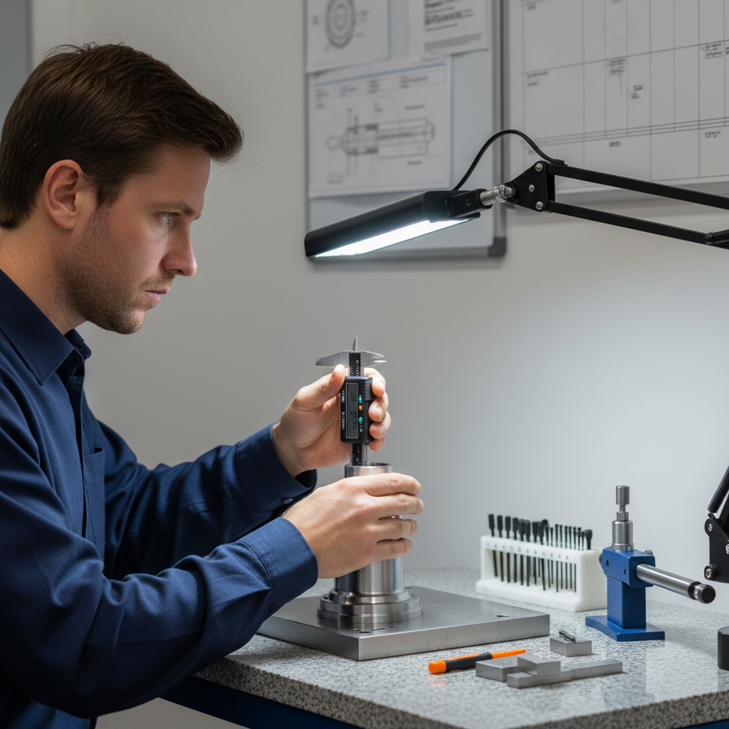
Moving from a standard ±0.005 inch tolerance to a high-precision ±0.0005 inch requirement is not a linear adjustment in effort; it is a fundamental shift in production strategy. This ten-fold increase in precision often triples the cost of a part. While the modern equipment at Anderson Manufacturing in Ephraim, Utah, is capable of such precision, the labor and time required to maintain it drive the price. These expenses generally stem from three primary cost drivers: cycle time, inspection overhead, and scrap rates.
First, cycle time increases as tolerances tighten. To hit a sub-thousandth dimension, machinists must use slower feed rates and shallower depths of cut to minimize tool deflection and thermal expansion. A feature that could be finished in one pass at a standard tolerance might require multiple finishing passes and frequent tool offsets. This limits the throughput of the machine, making each unit more expensive to produce.
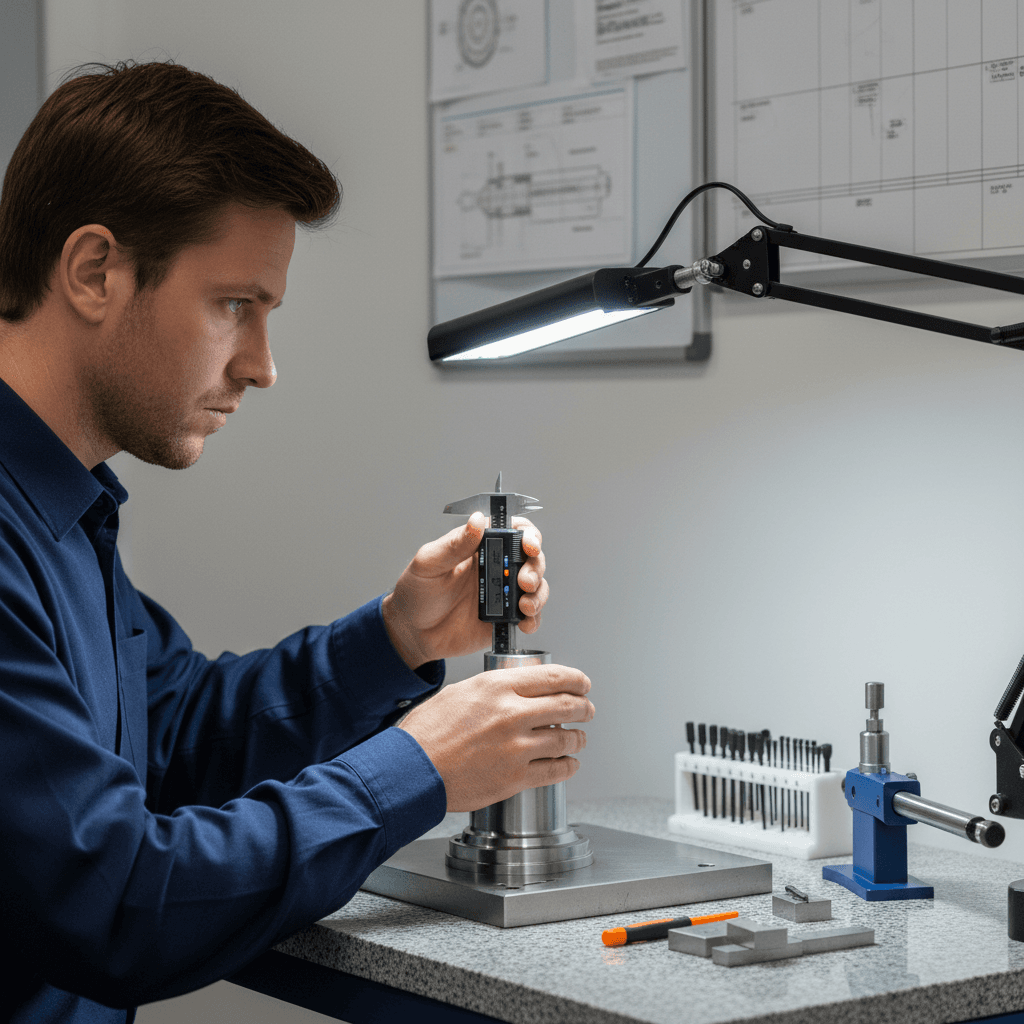
Second, inspection overhead scales with precision. For a simple clearance hole designed for a bolt, a machinist can verify the dimension quickly using a set of calipers or a go/no-go gauge. However, a press-fit bearing housing requires more sophisticated metrology. To confirm a ±0.0005 inch window, the part often needs to be measured with a Coordinate Measuring Machine (CMM) or specialized air gauges in a temperature-controlled environment. This additional handling time adds labor costs that are not present in standard precision manufacturing and fabrication services.
Finally, scrap rates represent a significant hidden cost. In any machining process, small variables like material batch consistency or subtle tool wear occur. In a ±0.005 inch window, these variables are easily absorbed. In a ±0.0005 inch window, a slight change in the shop's ambient temperature can push a part out of spec. Higher scrap rates mean the cost of rejected parts must be amortized across the successful units, raising the total quote.
Feature Type | Typical Tolerance | Impact on Cost Factors |
|---|---|---|
Clearance Hole | ±0.010" | High speed, manual inspection, low scrap |
Standard Mating Surface | ±0.005" | Balanced speed, standard tooling |
Press-Fit Housing | ±0.0005" | Slow speed, CMM inspection, higher scrap |
Because of these factors, the most cost-effective designs only utilize tight tolerances where they are functionally necessary. If you are analyzing a quote and suspect your specifications are driving costs higher than necessary, you can contact our engineering team to discuss where tolerances can be relaxed without compromising the final assembly's performance.
How to Specify Tolerances on Engineering Drawings Correctly

Accurately communicating design intent to a machine shop requires a strategic approach to documentation. For many basic parts, linear or coordinate tolerancing is the standard method. This approach uses plus/minus values on X, Y, and Z dimensions to define a rectangular tolerance zone. While simple to draft, coordinate tolerancing can occasionally lead to ambiguity in complex assemblies or issues with tolerance stacking, where the sum of several small variations exceeds the allowable limit for the final fit.
To solve this, many engineers utilize Geometric Dimensioning and Tolerancing (GD&T). Unlike coordinate tolerancing, GD&T uses a symbolic language to define the allowable variation based on the part’s actual function. It accounts for characteristics like flatness, parallelism, and true position relative to a datum, which is a fixed reference point. Because GD&T focuses on how parts interface or move rather than just idealized geometry, it often allows for a larger functional tolerance zone. This clarity helps Anderson Manufacturing in Ephraim, Utah produce functional components more efficiently by removing the guesswork during the setup and inspection phases.
The most effective drawings follow a Function First philosophy. Designers should only apply tight cnc machining tolerances to critical features, such as press-fits, seal grooves, or sliding surfaces, ensuring that precision manufacturing and fabrication services are applied where they add the most value. Non-functional edges, clearance holes, and external profiles should remain as loose as the design allows.
A common pitfall is the Title Block Trap. This occurs when a general note in the drawing's title block applies a strict global tolerance, such as ±0.001 inches, to every dimension not otherwise specified. This mistake forces the machinist to treat every chamfer and cosmetic edge with extreme precision, needlessly inflating the quote. Instead, use the title block for generous general tolerances and call out specific precision requirements only where they are functionally required. If you are refining a complex assembly, you can contact our engineering team to ensure your drawing conveys the right balance of precision and cost-effectiveness.
Is 0.1 mm a Tight Tolerance? Finding the Sweet Spot for Your Design
Determining whether 0.1 mm (approximately ±0.004 inches) constitutes a tight tolerance depends heavily on the material and the physical scale of the part. In the context of precision manufacturing and fabrication services, 0.1 mm is generally considered a standard, comfortable tolerance for most metal components. It sits right in the sweet spot where parts fit together reliably without requiring the expensive, slow machining processes associated with high-precision work.
By comparison, a tolerance of ±0.01 mm (±0.0004 inches) is a significant leap in complexity. Achieving this level of accuracy requires specialized machine setups, climate-controlled environments, and advanced metrology. While 0.1 mm can often be achieved with standard milling or turning operations, ±0.01 mm might necessitate secondary operations like grinding or honing to reach the final dimension.
Precision Level | Metric Tolerance | Imperial Equivalent | Production Impact |
|---|---|---|---|
Standard | ±0.1 mm | ±0.004" | High speed, standard tooling |
Precision | ±0.025 mm | ±0.001" | Moderate speed, careful setup |
High Precision | ±0.01 mm | ±0.0004" | Slow speed, specialized inspection |
Engineers should push for more precision only when the function demands it, such as for high-speed rotating shafts or press-fit assemblies. For external profiles, mounting brackets, or hand-held enclosures, sticking to the 0.1 mm range keeps projects at Anderson Manufacturing in Ephraim, Utah moving quickly and cost-effectively. If a part is exceptionally large or made of a thermally unstable plastic, even 0.1 mm can become difficult to maintain over time; therefore, always consider the material's physical properties before finalizing your cnc machining tolerances.
5 Design Tips to Optimize CNC Machining Costs Without Sacrificing Quality
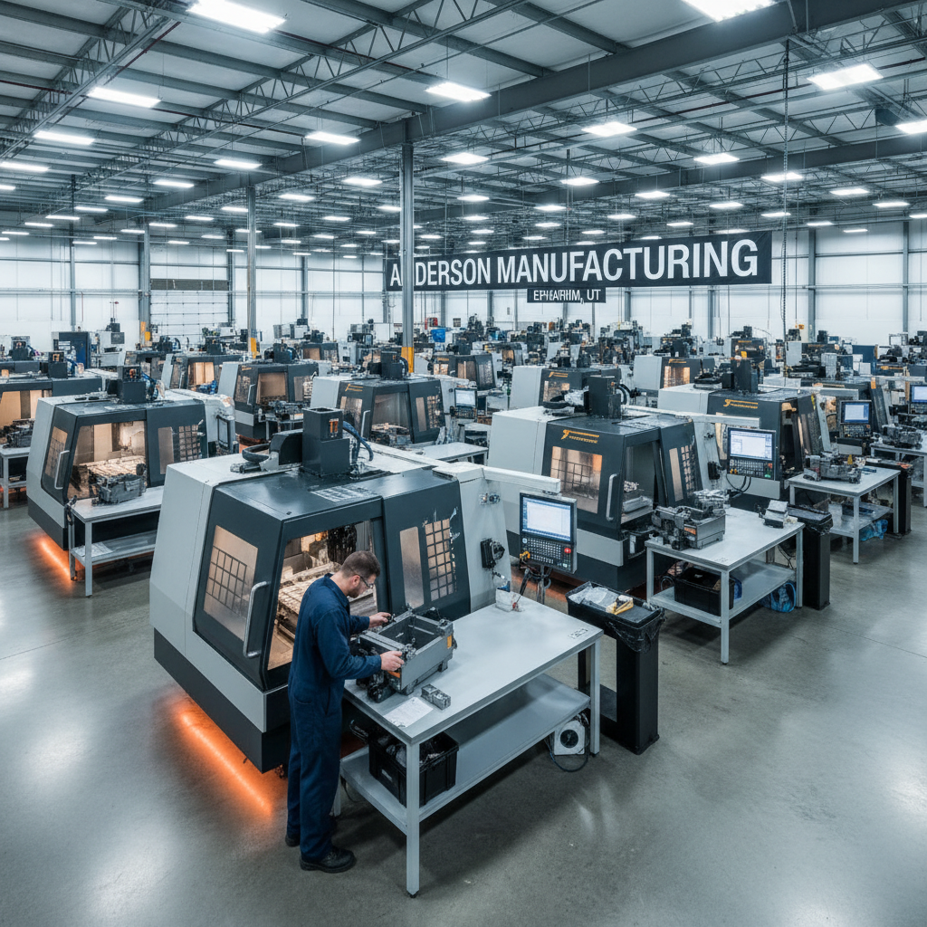
Optimizing a design for cost-efficiency requires a pragmatic look at how features are produced on the machine. By aligning specifications with standard shop capabilities, engineers can significantly reduce the price per part without losing functional integrity. Here are five practical tips for managing cnc machining tolerances and production costs:
Use standard hole sizes: Design holes to match off the shelf drill bits. When a diameter is specified that requires a custom boring bar or multiple interpolations with an end mill, it adds unnecessary cycle time. Sticking to fractional or metric standard sizes speeds up the drilling process.
Relax tolerances on non-mating surfaces: Features like exterior chamfers, aesthetic pockets, or clearance areas do not need the same precision as a bearing seat. Assigning a generous ±0.015 inch tolerance to these areas allows for faster roughing passes and fewer tool changes.
Specify GD&T only when necessary: Use Geometric Dimensioning and Tolerancing for critical assembly fitment, such as ensuring two holes are perfectly parallel or a surface is perfectly flat. Over-applying GD&T to simple parts can lead to complex inspection requirements that drive up the quote.
Account for material stability: Some materials, particularly plastics like Nylon or UHMW, are prone to warping or absorbing moisture. Attempting to hold a tight ±0.001 inch tolerance on these materials is often physically impossible once the part is removed from the machine and exposed to ambient conditions.
Minimize setup changes: Design parts that can be machined in as few orientations as possible. Every time a machinist must stop the cycle to flip or re-fixture a part, labor costs increase and the risk of tolerance stacking between setups rises.
At Anderson Manufacturing in Ephraim, Utah, our goal is to bridge the gap between complex engineering requirements and practical shop floor execution. We provide precision manufacturing and fabrication services that include a detailed design for manufacturability (DFM) review. By working with our clients to refine these specifications early, we ensure the final product hits the required quality benchmarks while remaining scalable and cost-effective. If you are ready to move from a prototype to a production run, you can contact our engineering team to discuss how to optimize your cnc machining tolerances for the best possible results.